
TRACE-Elevations: Wall, Roof and Opening Polygons from Vector Elevation Drawings
1. Introduction
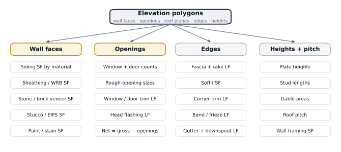
A floor plan tells an estimator how long the walls are. The elevations tell them what those walls are made of and how much of each. Siding by type, sheathing and weather-resistive barrier, stone and brick veneer, stucco, exterior paint, window and door counts and sizes, trim around every opening, corner boards, frieze and band boards, fascia, rake and soffit, gable-end areas and plate heights are all read from elevation views, usually by hand with a scale and a highlighter (Fig. 2).
The earlier TRACE reports addressed wall recovery on floor plans [7, 8] and roof recovery on roof plans [10]. Their central idea was that a construction PDF already contains exact vector geometry, so the learned part of the system should decide which drawn elements matter rather than redraw them. This report applies the same idea to elevations, where the geometry problem is different: the objects are areas rather than lines, and the drawing is dominated by hatch that looks like structure.
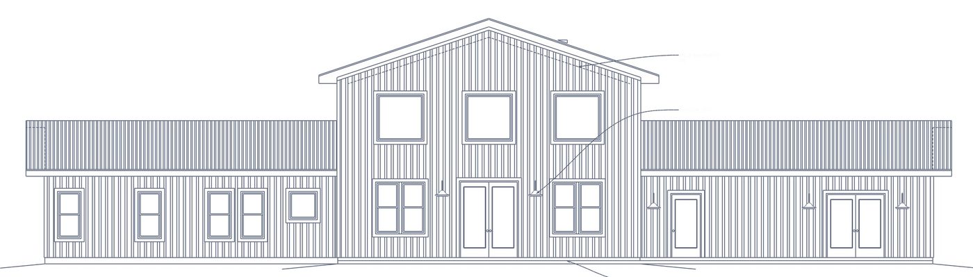
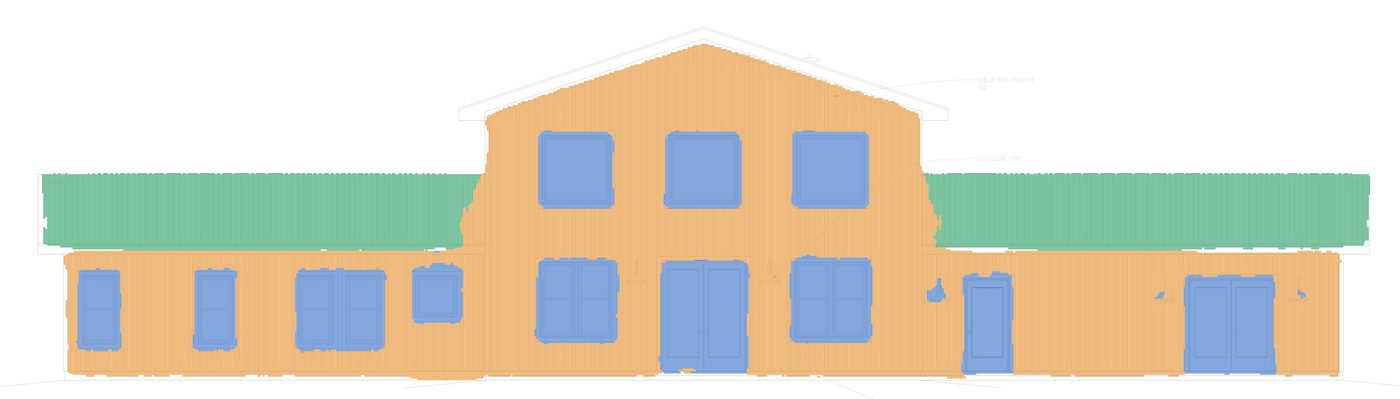
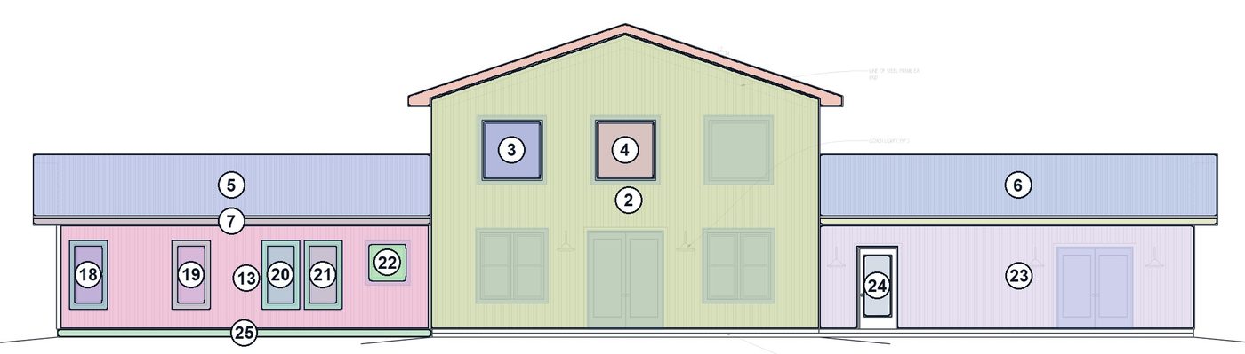
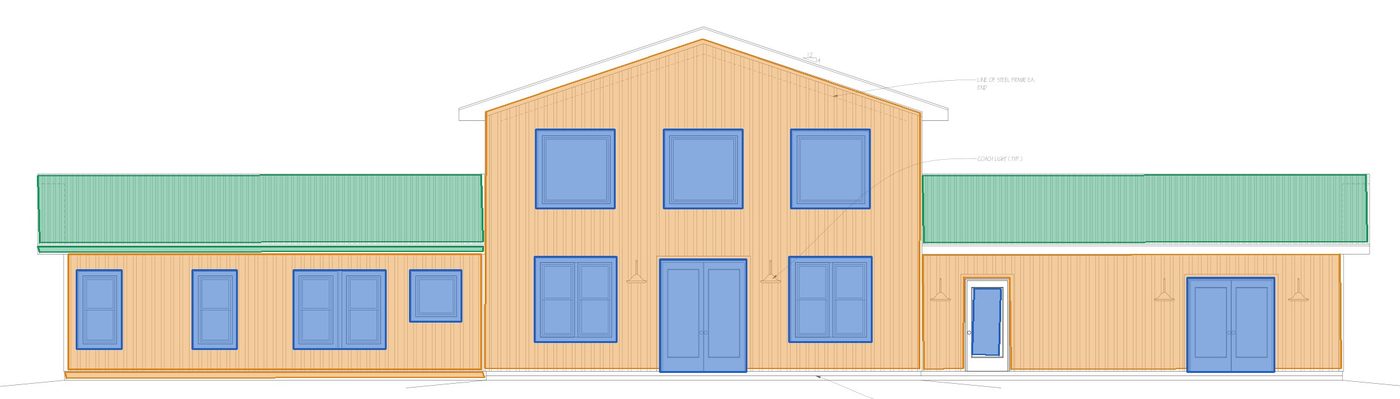
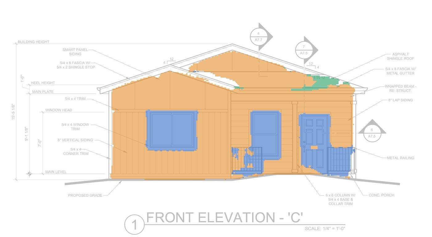
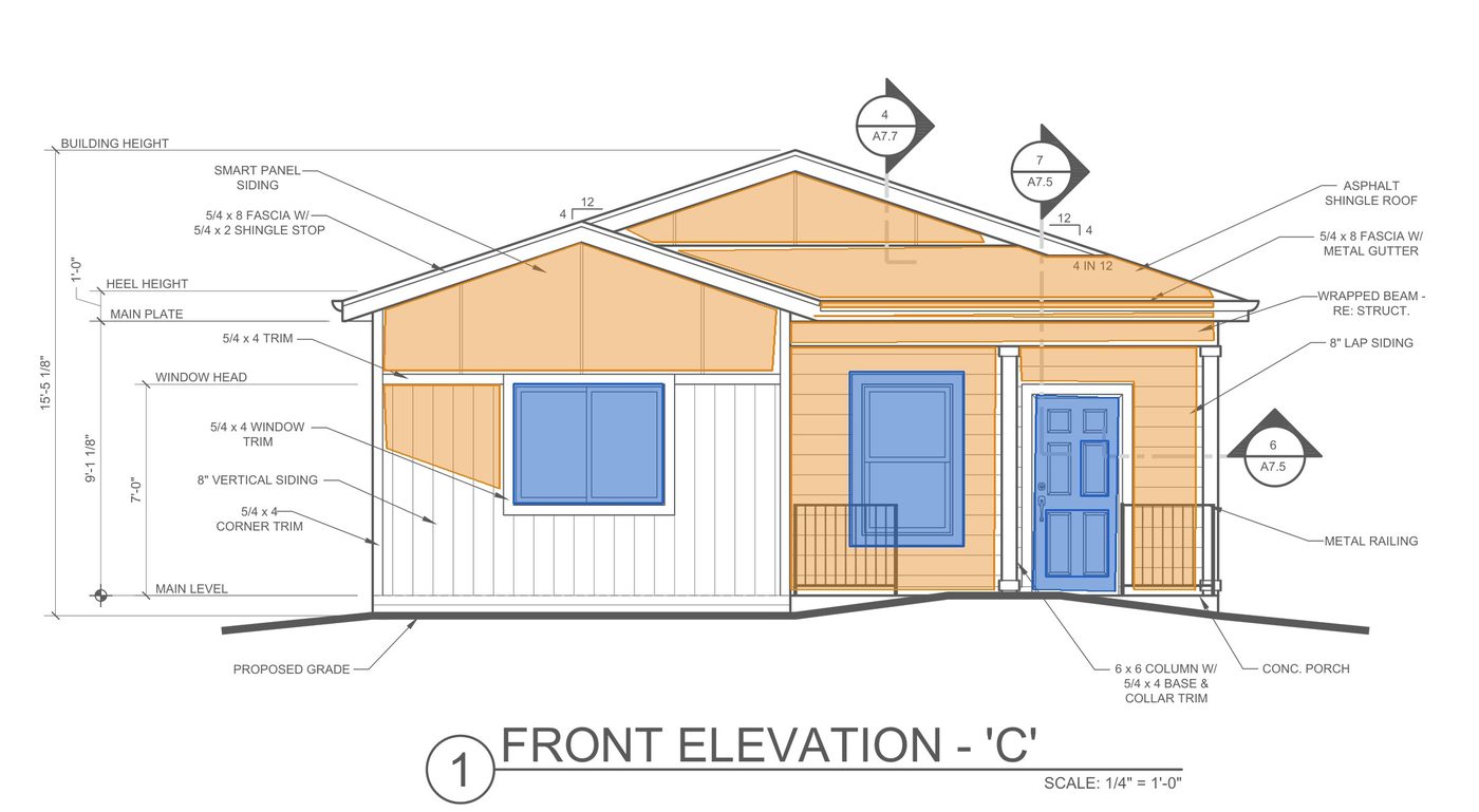
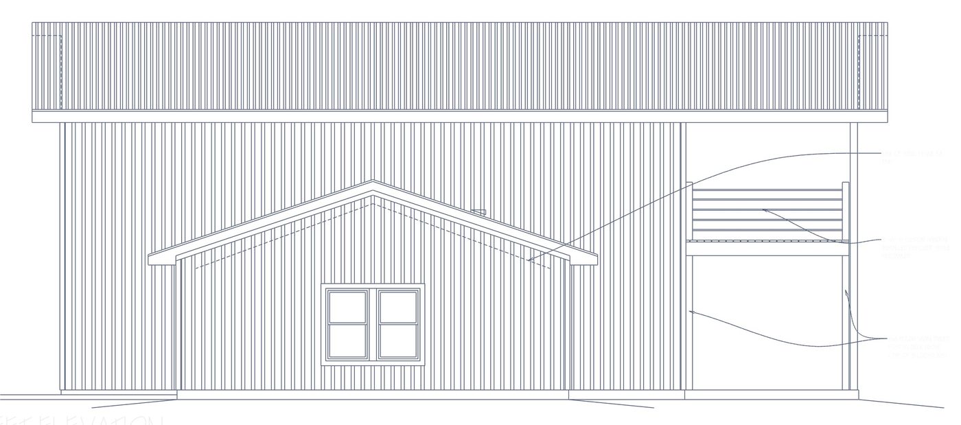
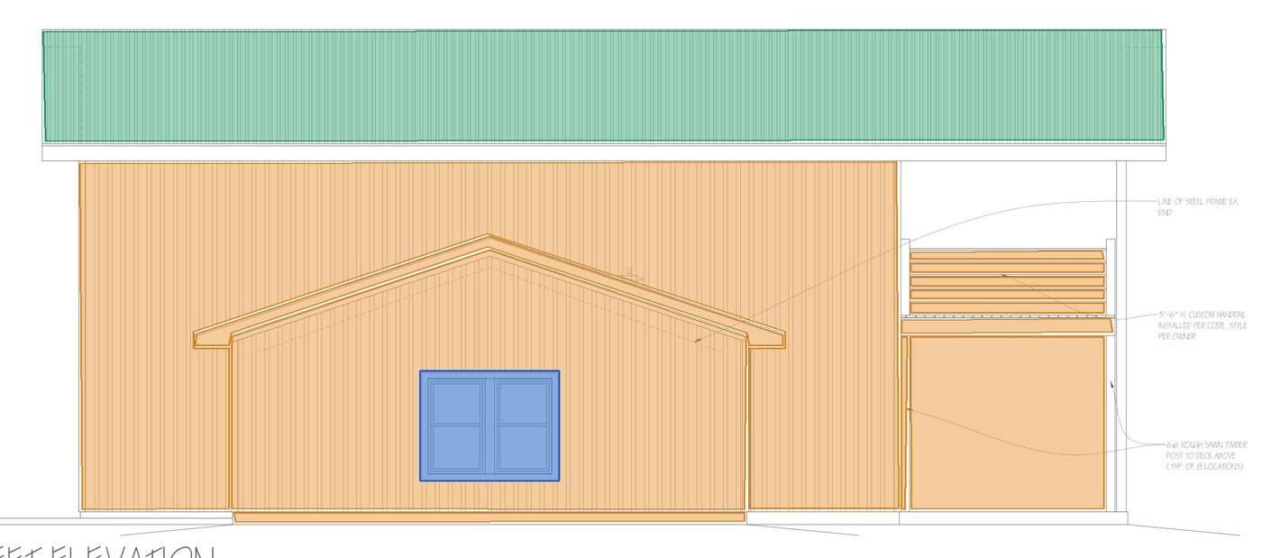
Figure 1(a) shows the difficulty. An ordinary residential elevation sheet at 1/4 in. = 1 ft carries thousands of vector segments, most of them board-and-batten, lap siding, shingle and metal-roof hatch, plus leaders, dimension lines, level markers and text. Nothing in the file says which closed area is a wall. A pixel classifier can learn the look of a wall (Fig. 1b), but its output is ragged at every edge and its square footage moves with that raggedness. An estimator needs edges that sit on the drawn lines.
The contributions of this pilot are:
- a pen-weight piece builder that uses the drafting convention of a heaviest outline pen to cut each elevation into a small number of closed pieces, with the outline pen chosen per sheet by self-grading rather than by a fixed rule;
- a vote-not-draw design in which a compact face model only labels pieces, and windows and doors come from boxes their own pen closes, so all output coordinates are PDF strokes;
- a pen census of real elevation sheets showing how often the convention is available and that pen order is not reliable across firms; and
- an honest pilot evaluation across model generations, including a self-training experiment that did not help and the failure classes that remain.
2. Related work
Most facade-understanding work starts from photographs. Teboul et al. segmented rectified facade images with procedural shape grammars [2], and the CMP Facade Database provided densely labeled facade photographs for learned parsing [3]. Photographs and construction drawings differ in kind: drawings have no texture or lighting, carry hatch patterns whose spacing encodes material, and overlay annotation on the object itself.
Floor-plan interpretation is closer in medium. Raster-to-vector methods recover walls and rooms from images [4], and CubiCasa5K supplied 5,000 annotated floor plans for multi-task parsing [5]. TRACE Residential and TRACE Commercial instead treat the vector CAD elements of the PDF as candidate tokens and learn only to verify them [7, 8], and TRACE-Roof applies the same idea to roof planes on roof plans [10]. TRACE-Elevations follows that line. The face model is a U-Net-style encoder–decoder [1], output polygons are simplified with the Douglas–Peucker algorithm [6], and the self-training experiment of Sec. 7.5 follows the pseudo-label idea of Lee [9].
3. Problem definition
3.1 Input and output
The input is one vector PDF page holding one or more elevations, plus a physical scale in PDF points per foot. Scale is read from the printed scale under each elevation title; when a sheet mixes scales the smallest elevation scale is used. The output is a set of polygons in PDF coordinates, each labeled wall face (with a material where one can be read), roof plane or opening, and the square footage each implies (Table 1).
| Quantity | Unit | Definition |
|---|---|---|
| Wall, gross | SF | wall-face polygons plus the openings inside them |
| Openings | SF, count | window and door frame boxes |
| Wall, net | SF | gross wall minus openings; the siding and sheathing basis |
| Wall by material | SF | net wall split by the material the face model reads |
| Roof, as drawn | SF | projected roof planes; true area needs the pitch and the roof plan |
| Edges | LF | polygon edges by neighbour: fascia, rake, corners, bands (planned) |
3.2 What counts as correct
A wall polygon is correct when its boundary follows the drawn outline of that face, so that its area is the face area at the stated scale. Openings are correct when the polygon is the window or door frame as drawn. Roofs in elevation are projections; their drawn area is reported as such and is not a roof takeoff. For this pilot each external sheet's full output is graded visually against the drawing as good (usable as drawn), partial (correct in part, needs correction) or bad (misleading). Pixel-level metrics on validation pages are reported separately (Sec. 7.2). A measured square-footage truth set does not yet exist; Sec. 10 returns to this.
4. Data
All pages come from Foreman AI's corpus of nearly 98,000 real engineered plans (about 3.6 million pages). Elevation pages are located automatically and rendered at 8 pixels per physical foot. Validation pages come from projects excluded from training; they were used to monitor the face model, not to update its weights.
The external evaluation set contains 171 elevation sheets, 114 residential or multi-family and 57 commercial, from plan sets that were never used for training. It spans hand-drafted-looking CAD, shaded renderings, colored material legends and scanned pages. Figures in this report use held-out validation sheets with neutral IDs (H1–H4) and are cropped to the drawing.
5. TRACE-Elevations
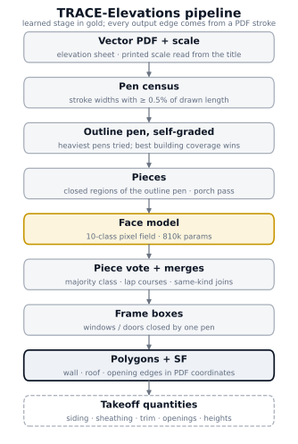
The pipeline is shown in Fig. 3 and Table 2. Only one stage is learned.
5.1 Pen census
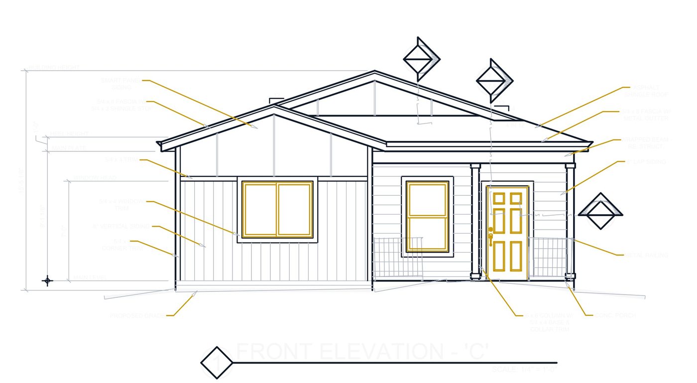
Every stroke in a PDF carries a width. The census sums drawn length per width and keeps pens that carry a meaningful share of it. Architectural convention assigns the heaviest pen to the building outline (wall edges, eaves, rakes, grade), a medium pen to windows, doors and trim, and light pens to hatch, dimensions and leaders. Figure 4(b) shows that convention on H2. It is common but not universal: we found sheets where windows are the lightest pen and lap siding the second, so the system never assumes what a given pen draws. It assumes only that the outline is the heaviest pen that actually draws the building.

5.2 Choosing the outline pen
The heaviest pen on a sheet is often not the outline: title-block borders, section-cut markers and cloud revisions can be heavier. TRACE-Elevations therefore tries each of the heaviest pens that carry at least 0.5% of drawn length and lets the sheet grade itself. For each candidate it closes small gaps (0.25 ft), finds the closed regions, discards paper, notes boxes and anything touching the sheet edge, and measures how much of what the face model calls wall or roof falls inside a closed region. The score is that coverage minus 0.001 per region, so a hatch pen that covers the building in hundreds of slivers loses to an outline pen that covers it in a few dozen pieces.
5.3 Pieces
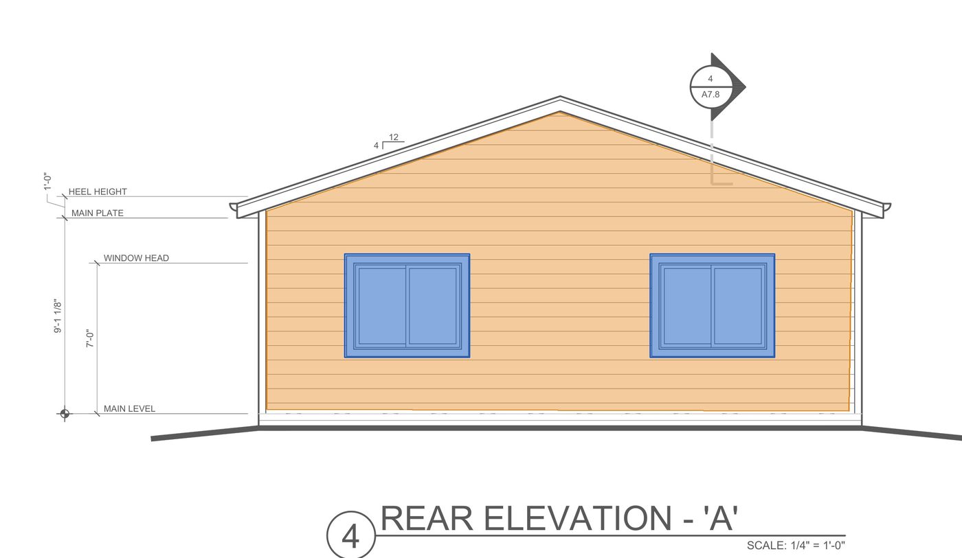
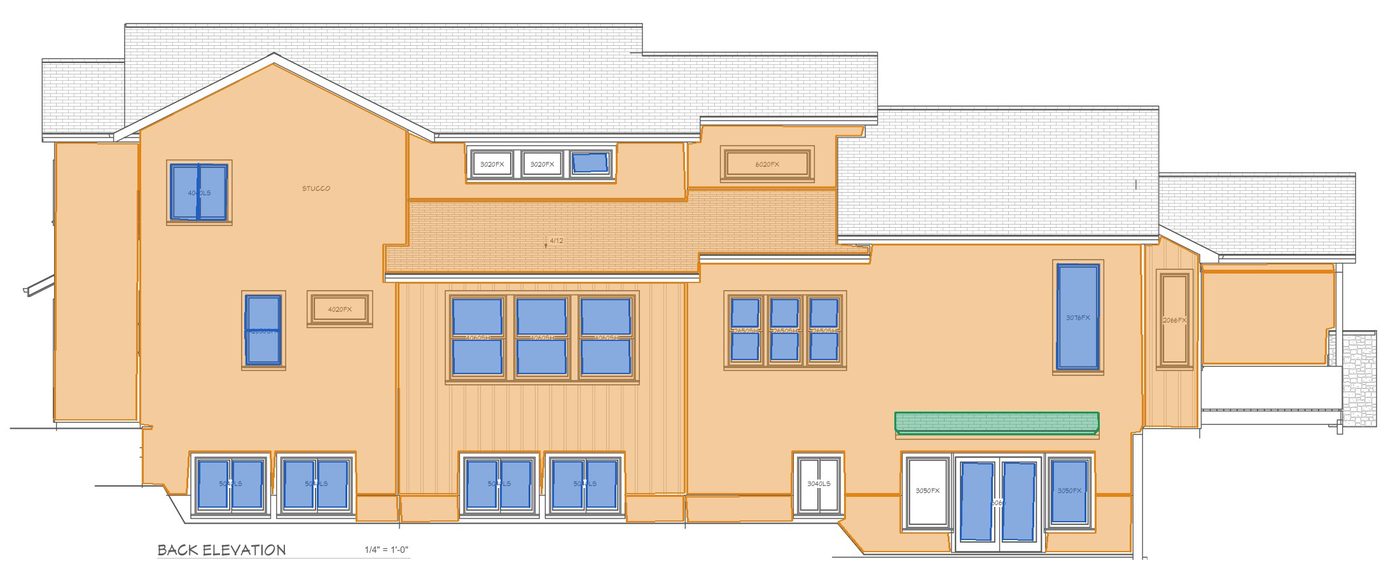
The chosen pen's closed regions become pieces. A second pass with the next pen picks up building the outline never closes, such as a porch drawn with posts. Enclosed unclaimed holes under 25 SF (the outline strokes themselves, slivers between siding courses, trim boards) join the nearest piece. Figure 1(c) shows the result: the rear elevation of H1 becomes about twenty pieces.
5.4 Face model
The face model reuses the RoomNet encoder–decoder body of TRACE Residential [7] with a 10-class softmax head: background, opening, roof, trim, wall of unknown material, masonry, lap, vertical, shingle and stucco. It has 810,174 parameters and runs at 8 pixels per foot. Where the material of a wall face cannot be read, the loss uses the negative log of the summed wall-class probability, so the model is not forced to guess a material the drawing does not show.
5.5 Piece vote and merges
Each piece takes the model's majority class when that class covers at least 70% of it; a mixed piece is re-split along the next pen down. Two merges then undo over-splitting. Wall pieces stacked less than 1.5 ft apart are bridged, because those gaps are the courses of lap siding that run out to the paper wherever a porch leaves the wall's sides open. And neighbouring pieces of the same kind that are separated only by a lighter pen (standing seams, panel joints, mullions) become one piece, while the outline pen still separates a gable from the wall below it.
5.6 Windows and doors
A window frame is a closed box drawn in one pen, while siding lines never close on their own because their ends are the wall outline or a window frame, both different pens. Each pen is therefore rasterized alone, and its connected drawings whose filled outline is box-shaped (at least 85% of the bounding box, aspect ratio at most 6, at least 0.75 ft across and 1.5 SF), lies inside a wall piece and is not mostly text becomes an opening. A box filling more than half of its host piece is the wall itself unless the model sees glass or a door there. Boxes are written as exact rectangles; arched heads keep their simplified outline.
5.7 Polygons
Piece outlines are simplified with Douglas–Peucker at 0.15 ft [6], which keeps square corners and roof pitch while removing the staircase of the raster. Polygons are written in PDF coordinates, so they overlay the source drawing exactly (Fig. 1d).
| Component | Role | Parameters |
|---|---|---|
| Pen census | stroke widths and their share of drawn length | deterministic |
| Outline pen selection | heaviest pens tried; coverage − 0.001 per region | deterministic |
| Piece builder | 0.25 ft seal · porch pass · holes < 25 SF absorbed | deterministic |
| Face model | RoomNet body, 10-class head, 8 px/ft | 810,174 |
| Piece vote | majority class ≥ 0.70, else re-split by the next pen | deterministic |
| Merges | lap gaps < 1.5 ft · same kind across lighter pens | deterministic |
| Frame boxes | one-pen boxes ≥ 1.5 SF inside wall pieces | deterministic |
| Polygon writer | Douglas–Peucker 0.15 ft · box openings squared | deterministic |
6. Training objective and generations
The face model is trained on 48 ft square crops at 8 px/ft with AdamW, warm-up and cosine decay, and 90° rotation and flip augmentation. The loss is cross-entropy over definite classes, the summed-wall term of Sec. 5.4, and a Dice term on the union of wall classes that keeps large flat faces from being absorbed by the background prior. Two augmentations proved useful. Material classes are collapsed into "wall" on pages where the material cannot be read reliably, while the face itself is kept. Shading augmentation paints random gray fills and ramps under the linework of walls, roofs and openings, so a clean line drawing looks like a shaded rendering; G4 was trained with this on half of all crops.
Five generations were trained (Table 3). G1 is the baseline; G2 added material classes; G3 expanded the training data and moved validation to projects fully excluded from training; G4 added shading augmentation; G5 added self-training from pieces (Sec. 7.5).
7. Results
7.1 External evaluation across generations
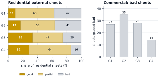
Figure 6 shows the visual grades of the full output on the external evaluation set. On residential sheets the good share rose from 10% (11 of 113) at G1 to 33% (38 of 114) at G3, and the bad share fell from 37% to 25% at G3 and 14% (16 of 112) at G4. G4 traded some good sheets for partial ones and removed most of the bad ones, chiefly shaded and colored renderings that G3 had misread. On commercial sheets bad results fell from 35 of 59 at G2 to 14 of 57 at G4.
7.2 Validation
On the shared validation set the face model reaches 0.980 face F1 at G3 and G5 and 0.978 at G4, opening IoU about 0.92 and roof IoU 0.82–0.83 (Table 3). Material classes remain weak at the pixel level (lap 0.45, vertical 0.46–0.50 IoU), which is one reason the piece vote reports a material only when a piece is dominated by one.
| Generation | Face P | Face R | Face F1 | Opening IoU | Roof IoU |
|---|---|---|---|---|---|
| G1 · baseline | 0.850 | 0.868 | 0.859 | 0.630 | 0.847 |
| G2 · + materials | 0.897 | 0.861 | 0.879 | 0.789 | 0.523 |
| G3 · expanded data, held-out projects | 0.971 | 0.989 | 0.980 | 0.916 | 0.815 |
| G4 · + shading augmentation | 0.968 | 0.988 | 0.978 | 0.917 | 0.820 |
| G5 · + piece self-training | 0.968 | 0.993 | 0.980 | 0.915 | 0.827 |
7.3 How often the convention is available
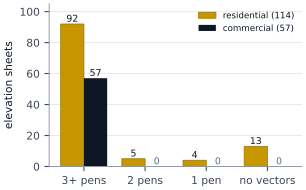
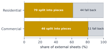
Figure 5 counts pens (stroke widths with at least 3 in. of drawn line) on all 171 external sheets. All 57 commercial elevations and 92 of 114 residential ones draw with three or more pens. Thirteen residential sheets have no vector linework (scans or pasted images), and nine draw with only one or two pens. The piece builder currently splits 70 of 114 residential sheets (61%) and 46 of 57 commercial sheets (81%) (Fig. 7); the remainder are the picture-based sheets, sheets drawn as filled shapes rather than strokes, and sheets where no candidate pen closes the building.
7.4 Qualitative results
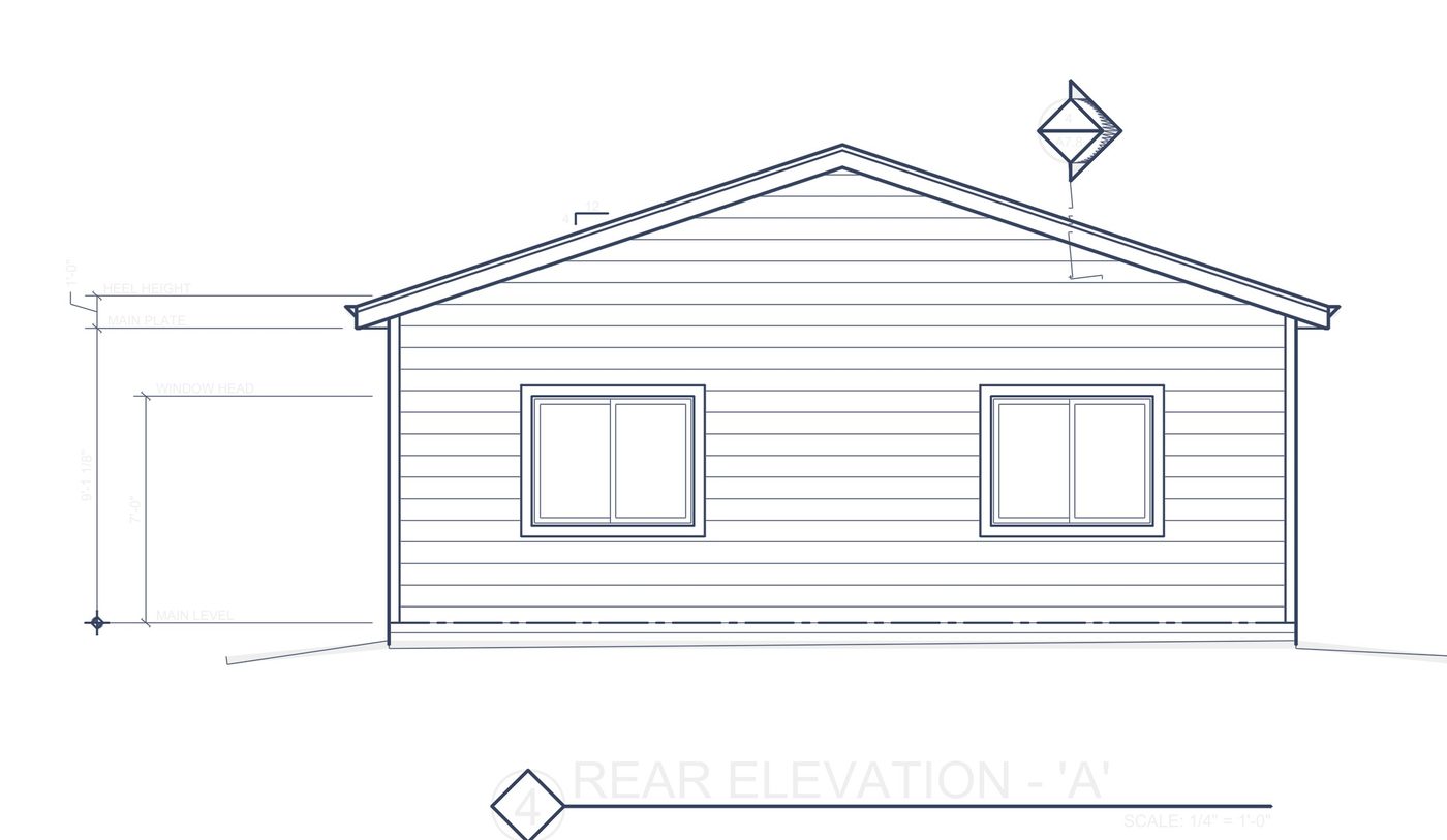
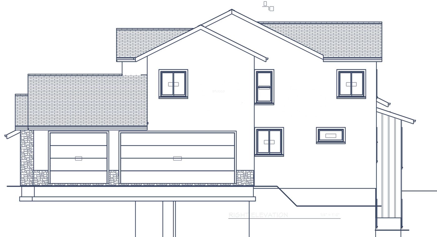
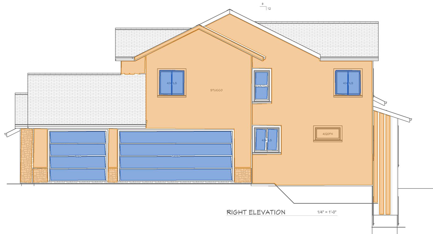
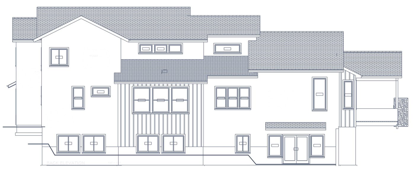
Figures 1, 8 and 9 show held-out elevations from the validation projects. Where the outline pen closes the building, results are close to what an estimator would draw by hand: one polygon per wall face, roof planes with their pitch, gables separated from the walls below them, and every window, door and garage door as a rectangle on its frame.
7.5 Self-training from pieces
Pieces make the model's own good output clean enough to learn from, which raw pixels are not. G5 tests this in the pseudo-label manner of [9]: confident pieces from external sheets that G3 or G4 had graded good were added as extra training signal, and 32 other external sheets, grouped by plan set, were held out for a blind comparison. Validation did not move (0.980), and a blind side-by-side on the 32 held-out sheets was a wash (Table 4): G5 fixed shaded roofs on one sheet, G4 was better on two, one was mixed, and the rest were within a few percent. Fifteen of the 32 held-out sheets produced no pieces at all. The remaining errors are not a data-volume problem.
| Held-out external sheets | Sheets | Share |
|---|---|---|
| Selected for the self-training test | 32 | 100% |
| No pieces (picture-based, scanned or not an elevation) | 15 | 47% |
| Pieces from both generations | 17 | 53% |
| Material difference, G5 better | 1 | |
| Material difference, G4 better | 2 | |
| Material difference, mixed | 1 | |
| Within a few percent | 13 |
8. Failure analysis
8.1 No vectors to split
The largest single gap is coverage. Scanned pages, sheets whose elevations are pasted in as images, and exports that draw outlines as filled shapes rather than stroked lines give the piece builder nothing to cut. In the self-training test these were 15 of 32 held-out sheets. They currently fall back to the pixel output snapped to whatever linework exists, which is less exact.
8.2 Shaded and hatched roofs
Roofs drawn with dense gray tile or shingle hatch are often left unclaimed or read as wall (Fig. 9). In those drawings the roof's gray tone is close to the shading some architects use on walls, and the pixel vote is split. The geometry already separates the roof plane cleanly; what is missing is a rule that a sloped piece above the eave line with open sky above it is a roof.
8.3 Missed faces and ground fill
Some faces are missed when their siding is drawn in a style the model has seen rarely, such as the vertical siding left of the window in Fig. 4(d). The opposite error also occurs on hillside sites: dark earth fill drawn below the grade line can be called wall. A grade-line rule (nothing below finished grade is siding) should remove most of it.
8.4 Doors and overhead doors
Swing doors are drawn as three-sided frames that stand on the grade line, so they never close as a one-pen box; roll-up and overhead doors with horizontal slats are sometimes voted wall when they form their own piece. Both need small geometric rules rather than more training.
9. Discussion
The central design choice carries over from TRACE on floor plans: the learned model never draws. On elevations this matters even more, because area quantities integrate every error along a boundary. A pixel field can be 98% right per pixel and still shift square footage along every ragged edge. Letting the drawing's own outline pen define the pieces turns that problem into a much smaller one: about twenty to fifty classification decisions per sheet, each of which an estimator can see and correct with one click.
The pen census is the second lesson. A drafting convention is true often enough to build on but never safe to hard-code. Self-grading the outline pen, and finding openings as single-pen boxes regardless of which pen draws them, keeps the convention as a prior rather than a rule.
The self-training result is the third. Volume is not the bottleneck. The failure classes in Sec. 8 are specific, visible and mostly geometric, and the next gains are expected from rules that use the pieces' own geometry (sky above, grade below, eave line, hatch spacing, pen weight, nearby keynote text) rather than from more pixel training.
10. Limitations
- Visual grading. External results are good/partial/bad grades of the full output, not measured square-footage error. A truth set of hand-measured wall, opening and roof areas is the next requirement.
- Grader. Grades were assigned by visual review with AI assistance and not repeated by a second reviewer. G1–G2 validation sets also differ from G3–G5.
- Coverage. The piece builder splits 61% of residential external sheets; the rest use a less exact fallback.
- Materials. Pixel-level material accuracy is low; material SF is reported only where one material dominates a piece.
- Edges and heights. Fascia, rake, corner and band lengths and plate heights are planned but not evaluated here.
11. Next steps
Three steps follow directly. First, a geometric piece classifier that adds sky-above, grade-below, eave-line, hatch-spacing, pen-weight and keynote-text features to the model's vote, aimed at the roof and ground-fill errors. Second, a fallback for picture-based sheets that snaps the pixel field to whatever linework exists and, for true scans, to detected edges. Third, a measured benchmark of hand-measured wall, opening and roof areas on a building-disjoint set, scored as square-footage error per sheet.
12. Conclusion
TRACE-Elevations shows that the TRACE principle (keep coordinates in the PDF and let learning only decide what the drawn elements are) extends from floor-plan walls to elevation areas. The heaviest pen cuts an elevation into a few dozen pieces, a compact face model votes on them, and single-pen boxes give exact windows and doors. Across four generations the share of residential external sheets graded good tripled and the share graded bad fell by more than half. The remaining failures are specific and geometric, and the next decisive result is not another training run but a measured square-footage benchmark.
Data availability
The plan sheets come from Foreman AI's proprietary corpus and are not redistributed; sheets are identified by neutral IDs and figures are cropped to the drawing. Checkpoints, per-sheet grades and census results are retained by Foreman AI Research.
Competing interests
Kyle Rossignol is the founder of Foreman AI LLC, which develops commercial construction-estimating software incorporating the technology described here. This manuscript reports internal research and should be interpreted with that relationship disclosed.
Funding
The work was conducted as internal research and development by Foreman AI LLC. No external research funding is reported.
Author contributions
K.R. conceived the elevation-takeoff problem, directed the research program, and set the evaluation priorities. The piece builder, experiments, figures and this manuscript were prepared with Claude (Anthropic), an AI model, under K.R.'s direction.
References
- O. Ronneberger, P. Fischer, and T. Brox, “U-Net: Convolutional Networks for Biomedical Image Segmentation,” in Medical Image Computing and Computer-Assisted Intervention (MICCAI), pp. 234–241, 2015.
- O. Teboul, L. Simon, P. Koutsourakis, and N. Paragios, “Segmentation of Building Facades Using Procedural Shape Priors,” in Proc. IEEE Conference on Computer Vision and Pattern Recognition (CVPR), 2010.
- R. Tyleček and R. Šára, “Spatial Pattern Templates for Recognition of Objects with Regular Structure,” in Proc. German Conference on Pattern Recognition (GCPR), 2013.
- C. Liu, J. Wu, P. Kohli, and Y. Furukawa, “Raster-To-Vector: Revisiting Floorplan Transformation,” in Proc. IEEE International Conference on Computer Vision (ICCV), pp. 2195–2203, 2017.
- A. Kalervo, J. Ylioinas, M. Häikiö, A. Karhu, and J. Kannala, “CubiCasa5K: A Dataset and an Improved Multi-Task Model for Floorplan Image Analysis,” arXiv:1904.01920, 2019.
- D. H. Douglas and T. K. Peucker, “Algorithms for the Reduction of the Number of Points Required to Represent a Digitized Line or its Caricature,” Cartographica, vol. 10, no. 2, pp. 112–122, 1973.
- K. Rossignol, “TRACE Residential: Candidate-Then-Verify Wall Recovery from Vector Construction Drawings,” Foreman AI Research, TRACE Series Report 1, Colorado, USA, Sep. 2026.
- K. Rossignol, “TRACE Commercial: Adapting Wall Recovery to Commercial Floor Plans,” Foreman AI Research, TRACE Series Report 2, Colorado, USA, Sep. 2026.
- D.-H. Lee, “Pseudo-Label: The Simple and Efficient Semi-Supervised Learning Method for Deep Neural Networks,” in ICML Workshop on Challenges in Representation Learning, 2013.
- K. Rossignol, “TRACE-Roof: A Pilot for Recovering Roof Area, Roof Lines and Roof Planes from Architectural Roof Plans,” Foreman AI Research, TRACE Series Report 3, Colorado, USA, Sep. 2026.